|
|
|
|
|
|
 |
 As their name implies, Better Light’s digital scanning backs do not capture an image of the subject in front of the camera all at once, but rather by physically moving a unique, highly-optimized trilinear color image sensor smoothly across the image plane, building up the image one line per color at a time. As their name implies, Better Light’s digital scanning backs do not capture an image of the subject in front of the camera all at once, but rather by physically moving a unique, highly-optimized trilinear color image sensor smoothly across the image plane, building up the image one line per color at a time.
This means that scanning backs are typically used only for photographing relatively stationary subjects illuminated by continuous light. Continuous advancements in image sensor and processing hardware and software over the past decade have made these high-resolution capture devices much faster and easier to use, but scanning backs will probably not be used for fashion or sports photography any time soon. However, wherever appropriate subject and lighting conditions permit, there is no finer method of direct digital image capture than a skilled photographer with a Better Light scanning back in a large-format camera.
All of our scanning back models utilize high-performance Kodak trilinear color image sensors that provide much more than just a lot of pixels. In addition to having up to 10,200 flawless red, green, and blue pixels across their 72mm active width, these sensors also feature some of the highest full-well capacities in the industry, for unmatched dynamic range in real-world conditions.
|
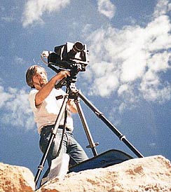
Well known landscape photographer, Stephen Johnson of Pacifica, CA, has traveled the world with his view camera and Better Light scanning back to capture nature at it's best. www.sjphoto.com
|
 |
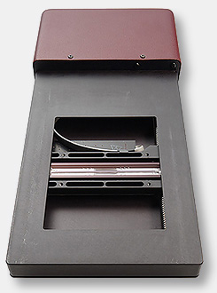
The trilinear sensor is mounted in a ball bearing carriage that glides on a precision track cut into the metal body frame, and is accurately positioned by a matched polymer nut and stainless steel drive screw directly coupled to a high-torque step motor with up to 6400 micro-steps per revolution, for outstanding smoothness at any motor speed. This motor is driven by a dedicated microcontroller that also controls the sensor’s exposure and timing, for crystal-accurate synchronization of these important functions.
 Within the image sensor, three rows of light-sensitive photodiodes are each covered by a red, green, or blue color filter, making the entire row sensitive to only one primary color. While Kodak’s trilinear sensors use CCD (charge-coupled device) technology like many other digital cameras, in these devices the CCD structures are “blind” (not sensitive to light), and serve only as charge transport “conveyor belts” to carry the individual pixel signals from the photodiodes to an output amplifier for each row. Because there is no need to have the three rows of photodiodes immediately adjacent to each other, a wide CCD structure is positioned adjacent to each row of photodiodes, with the necessary electrical couplings between them. The CCD structure is wider than the photodiode structure so it can carry bigger charge packets (more electrons), which improves dynamic range. Within the image sensor, three rows of light-sensitive photodiodes are each covered by a red, green, or blue color filter, making the entire row sensitive to only one primary color. While Kodak’s trilinear sensors use CCD (charge-coupled device) technology like many other digital cameras, in these devices the CCD structures are “blind” (not sensitive to light), and serve only as charge transport “conveyor belts” to carry the individual pixel signals from the photodiodes to an output amplifier for each row. Because there is no need to have the three rows of photodiodes immediately adjacent to each other, a wide CCD structure is positioned adjacent to each row of photodiodes, with the necessary electrical couplings between them. The CCD structure is wider than the photodiode structure so it can carry bigger charge packets (more electrons), which improves dynamic range.
Because of this dual photodiode/CCD structure, these sensors can be reading out three previous rows of color pixel information via the CCD structures while the next three rows of color pixels are being collected in the photodiodes. This allows continuous exposure and readout of the sensor during a scan, without requiring any mechanical shutter. Better Light scanning backs do not stop and start the scanning mechanism to allow the data-collection system to “catch up” – instead, the sensor is always moved smoothly and continuously throughout each capture.
|
| |
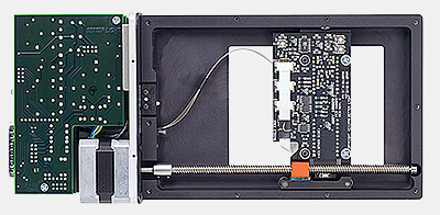
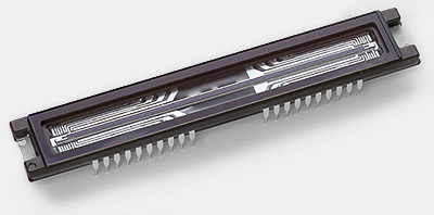
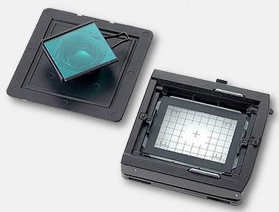
The open back of the scanning insert shows the circuit board that the Kodak CCD is mounted on. The sensor glides on a precision track in a smooth, continuous movement during the image exposure. |
|
 |
|
|
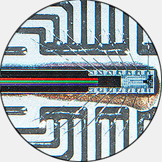
Within the image sensor, three rows of light-sensitive photodiodes are each covered by a red, green, or blue color filter, making the entire row sensitive to only one primary color. The magnified view of the Kodak trilinear sensor (right) shows the red, green and blue filtered sensors and part of the charge transport assembly that carries the electrical signals from the photodiodes to the output amplifiers. |
|
|
|
|
 As each three rows of pixels complete their exposure, the accumulated packets of charge representing each pixel are transferred to the adjacent CCD structures, which also empties the photodiodes to begin the next rows’ exposure immediately. The packets of charge get moved by the CCD structures down the entire length of the image sensor, where they are individually converted to voltages and amplified before leaving the chip. An entire row of pixels must be transported down the CCD and off the chip before the next row of pixels gets dumped into the CCD structures. As each three rows of pixels complete their exposure, the accumulated packets of charge representing each pixel are transferred to the adjacent CCD structures, which also empties the photodiodes to begin the next rows’ exposure immediately. The packets of charge get moved by the CCD structures down the entire length of the image sensor, where they are individually converted to voltages and amplified before leaving the chip. An entire row of pixels must be transported down the CCD and off the chip before the next row of pixels gets dumped into the CCD structures.
As the sensor moves across the image area, red, green, and blue pixel signals pour out as three separate analog streams from the device. All Better Light scanning backs feature individual variable analog gain amplifiers for each color channel that can be precisely adjusted from a gain of unity to over 16 times amplification, with thousands of digitally-controlled intermediate settings. These variable gain amplifiers are used to establish an exact neutral balance under nearly any lighting conditions, and also to change the ISO sensitivity of the scanning back over a range of up to four f-stops. High-speed analog signal processing circuitry for each color uses double-correlated sampling to obtain an accurate value for each pixel prior to being digitized by three separate 14-bit analog-to-digital converters operating in parallel. 48 bits of RGB pixel data is multiplexed 8 bits at a time across a high-speed unidirectional data cable that also includes low-speed bidirectional serial communications and power for the scanning back.
At the other end of the cable (inside the control box), a FIFO buffers incoming pixel data in preparation for processing by a high-speed digital signal processor (DSP). Using a table of CCD gain correction values determined and loaded at the factory for each device, and another table of CCD dark signal values obtained just before each scan, the DSP corrects each incoming pixel value for minor variations in dark signal (black offset) and gain (white level), and even for changes in dark signal caused by thermal drift. Unlike conventional digital cameras, all of the pixels on our Kodak trilinear sensors are guaranteed to work properly within narrow limits – this digital signal processing eliminates any minor variations among pixels for consistent performance across the entire array, from dark to bright.
The DSP also performs half of any Resolution reduction or enhancement requested by the software, to provide a range of output file sizes for different applications. The other half of any Resolution change is performed by the scanning mechanism, which simply moves the image sensor faster or slower relative to the rate that lines (rows of pixels) are being exposed, thereby quite literally adjusting the number of lines per millimeter that are being recorded. Along the image sensor (row) axis, however, there are always a fixed number of pixels, so the DSP can add parts of several pixels together to make fewer, effectively larger pixels, or it can cut pixels apart to make more, effectively smaller pixels. Adding parts of several pixels together does lower the optical resolution of the system as expected, but cutting pixels apart does not increase the optical resolution of the system beyond the native resolution of the sensor.
|
 |
|
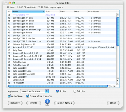
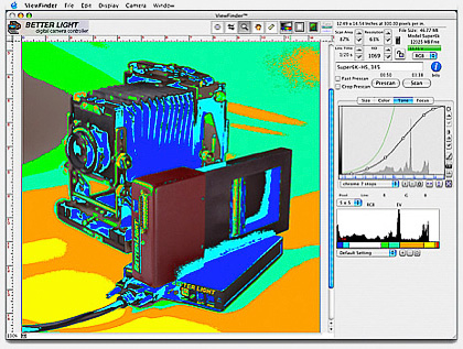
CAMERA FILE MANAGER: Included in every Better Light system is a dedicated hard disk drive (inside the control box), which is used for immediate storage of all scanned images (except prescans). The disk drive in a Better Light system is under the direct control of the system’s microprocessor, for real-time data handling at the limits of the hardware. The drive uses a simple, proprietary filing system to store image data in contiguous blocks, so there is no disk “fragmentation” possible other than by leaving old files scattered on the drive. Image files saved on this drive are accessed, retrieved to the host computer, and/or deleted using Better Light’s ViewFinder software. The drive does not appear on the computer’s desktop, and it is not possible to write anything (except image notes) back to the drive.
|
|
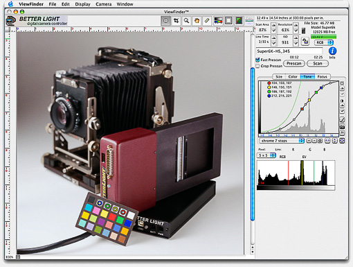
Like many other scanners, our scanning backs can generate a fast, low-resolution prescan image that is an accurate representation of the final scan’s composition and exposure, but takes much less time to complete. Unlike many other scanners, our software features interactive editing of the system’s exposure parameters, with any changes displayed immediately on the existing prescan image data, without requiring another prescan. Also unlike many other scanners, there is no fixed light source used with our scanning backs, and scene illumination can vary over a tremendous range. Thus, our ViewFinder software has exposure controls that will be more familiar to a photographer than to a scanner operator. Very precise control of exposure, ISO sensitivity, and color balance is possible using the controls in this software, and there isn’t any “auto-exposure” function, although the interactive nature of these adjustments makes it quite easy to determine the proper settings based on visual and digital feedback from the displayed prescan image. Once all parameters are satisfactory, the final scan is captured, after which the image data is immediately available for retrieval and examination in a third-party image viewer/editor such as Adobe Photoshop.
|
|
|
Using a Better Light scanning back is very straightforward, especially if one already has experience with a 4x5 view camera. The scanning area of all Better Light models is the same – 72 x 96 mm – which is slightly smaller than 4x5 film. Better Light systems include several ground glass viewing overlays with a low-tack adhesive that can be mounted on the camera’s ground glass to show the scanning area, allowing proper composition of the image. This smaller-than-4x5 image area also means that there will be a slight “telephoto effect”, with the lens behaving like a slightly longer focal length (due to the reduced coverage).
 The only other modification to the view camera is the addition of an infrared-blocking filter in the optical path, usually on either side of the lens. This “IR filter” blocks near-infrared wavelengths from 700 to 1000 nanometers that would otherwise pollute the color response of the image sensor and produce washed-out images. Two different densities of IR filter are supplied for different types of lighting, allowing optimum image capture conditions with a variety of light sources. Intentionally omitting this filter allows the sensor to capture a near-infrared image with all three color channels, while each color channel still retains its response to visible light of the proper color. The only other modification to the view camera is the addition of an infrared-blocking filter in the optical path, usually on either side of the lens. This “IR filter” blocks near-infrared wavelengths from 700 to 1000 nanometers that would otherwise pollute the color response of the image sensor and produce washed-out images. Two different densities of IR filter are supplied for different types of lighting, allowing optimum image capture conditions with a variety of light sources. Intentionally omitting this filter allows the sensor to capture a near-infrared image with all three color channels, while each color channel still retains its response to visible light of the proper color.
After installing the IR filter and ground glass viewing overlay, the camera is focused and composed as usual, keeping the desired image within the bounds of the overlay. All normal view camera movements are allowed – the sensor will capture an image as long as light is falling on its front surface, from nearly any angle. Once the camera has been adjusted and focused, a Better Light scanning back is inserted into the camera’s film slot, just like a (big, heavy) film holder.
|
|
 Because our ViewFinder software uses familiar photographic terminology, it is possible to use traditional photographic exposure tools, like a spot meter, to help determine the proper exposure setting for each image. However, one soon realizes that each prescan image is essentially three-quarters of a million spot meter readings, each in full color and with digital accuracy, as recorded by the same device that will ultimately capture the final image, and the spot meter soon gets left behind. In addition to providing pixel-by-pixel readout of red, green, and blue data values, ViewFinder software features “ToneZones™” false-coloring of the prescan image according to predefined data values, for immediate identification of over- or under-exposure conditions without having to probe around. These digital metering capabilities, plus the interactive display of any exposure changes on the existing prescan image, make it easy to determine the correct exposure for each image, with as much or as little digital precision as one desires. Because our ViewFinder software uses familiar photographic terminology, it is possible to use traditional photographic exposure tools, like a spot meter, to help determine the proper exposure setting for each image. However, one soon realizes that each prescan image is essentially three-quarters of a million spot meter readings, each in full color and with digital accuracy, as recorded by the same device that will ultimately capture the final image, and the spot meter soon gets left behind. In addition to providing pixel-by-pixel readout of red, green, and blue data values, ViewFinder software features “ToneZones™” false-coloring of the prescan image according to predefined data values, for immediate identification of over- or under-exposure conditions without having to probe around. These digital metering capabilities, plus the interactive display of any exposure changes on the existing prescan image, make it easy to determine the correct exposure for each image, with as much or as little digital precision as one desires.
EXPOSURE TIME = RESOLUTION (number of lines) X LINE TIME
Final scans will take anywhere from less than a minute to ten minutes or more, depending primarily upon the amount of light available to the sensor, and on the number of lines in the overall scan. In all cases, the overall scan time is simply the product of the exposure time per line (called the Line Time) multiplied by the number of lines in the scan. A wide range of Line Time and ISO settings allows the operator to optimize performance in lower-light conditions based on the desired image quality level and the amount of time available for the scan.Better Light scan backs include a dedicated disk drive in the control box where image data is stored during each scan. Fast, high-resolution scans can generate up to 12 MB per second of pixel data, which is written to the disk drive without pausing during the entire scan. Each image is stored in a single block – there is no “fragmentation” of files on this drive, as commonly occurs with computer disk drives. This single-block requirement also ensures smooth track-to-track head seeks of the drive during each scan, to avoid longer pauses in the data flow caused by head seeks to other parts of the drive. After a scan is completed, all of the files on the unit’s disk drive can be listed by using the File Manager in ViewFinder software (see inset above). One or more image files can be selected and retrieved to any available storage medium in the host computer. Images are saved as standard TIFF files with either 8 or 16 bits per channel of monochrome or RGB data. Once in the host computer, these TIFF files can be viewed using a high-performance image editing application such as Adobe Photoshop (but not by ViewFinder software).
|
| |
|
|
|
|
|
|
|
|